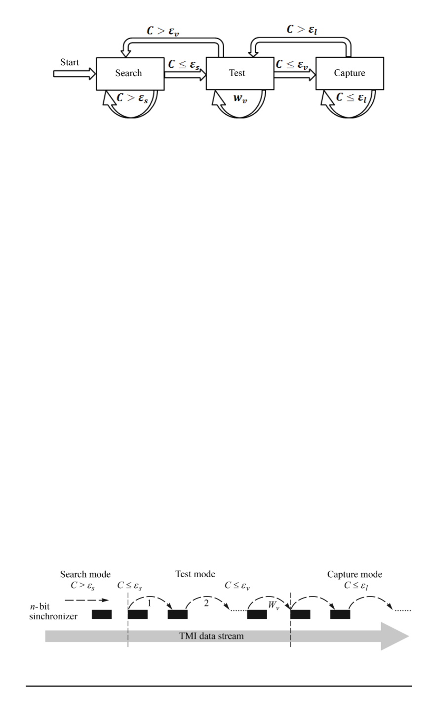

Fig. 2. Transition between the TMI stream frame synchronizer states
Fig. 2 shows transitions between the synchronizer states: “Search”,
“Test” and “Capture”, where
ε
l
is the synchronizer threshold in the “Search”
mode,
ε
v
— in the “Test ” mode, and
ε
l
— in the “Capture” mode;
C
is a correlation coefficient, equal to the value
L
(
μ
)
calculated based
on formula (2). In each state, if the value of the correlation coefficient
C
is either less than or equal to the threshold of the current state, the
synchronization code is considered to be detected and vice versa.
At the beginning of its operation, the synchronizer is in the “Search”
state. If the synchronizer detects the synchronization code (
C
≤
ε
s
), it
proceeds to the “Test” state. If in the “Test” state the number of detected
consecutive synchronization codes (
C
≤
ε
v
) reaches a predetermined value
w
v
, the synchronization system proceeds to the “Capture” state, otherwise,
the system returns to the “Search” mode. In the “Capture” mode the frame
synchronization is provided. When the synchronization code exceeds the
threshold
ε
l
, the synchronizer returns to the “Test” mode. In the “Search”
mode the synchronizer reads bits until it detects the synchronization code
in a stream, and then in the “Test” and “Capture” modes it shifts in the
stream to a step length. A step length is equal to the TMI frame length, as
it is shown in Fig. 3.
The purpose of this work is to develop methods of calculation and
selection of frame synchronizer parameters, including thresholds
ε
s
for
the “Search” state,
ε
v
— for the “Test” state and
ε
l
— for the “Capture”
state, as well as the avarage synchronizer latency
w
v
in the “Test” mode,
where the value
w
v
is represented by the average number of frames. The
synchronization system parameters are selected for the telemetry frame of
Fig. 3. Shift of the synchronizer in telemetry data stream in various operating modes
ISSN 0236-3933. HERALD of the BMSTU. Series Instrument Engineering. 2015. No. 2 119


