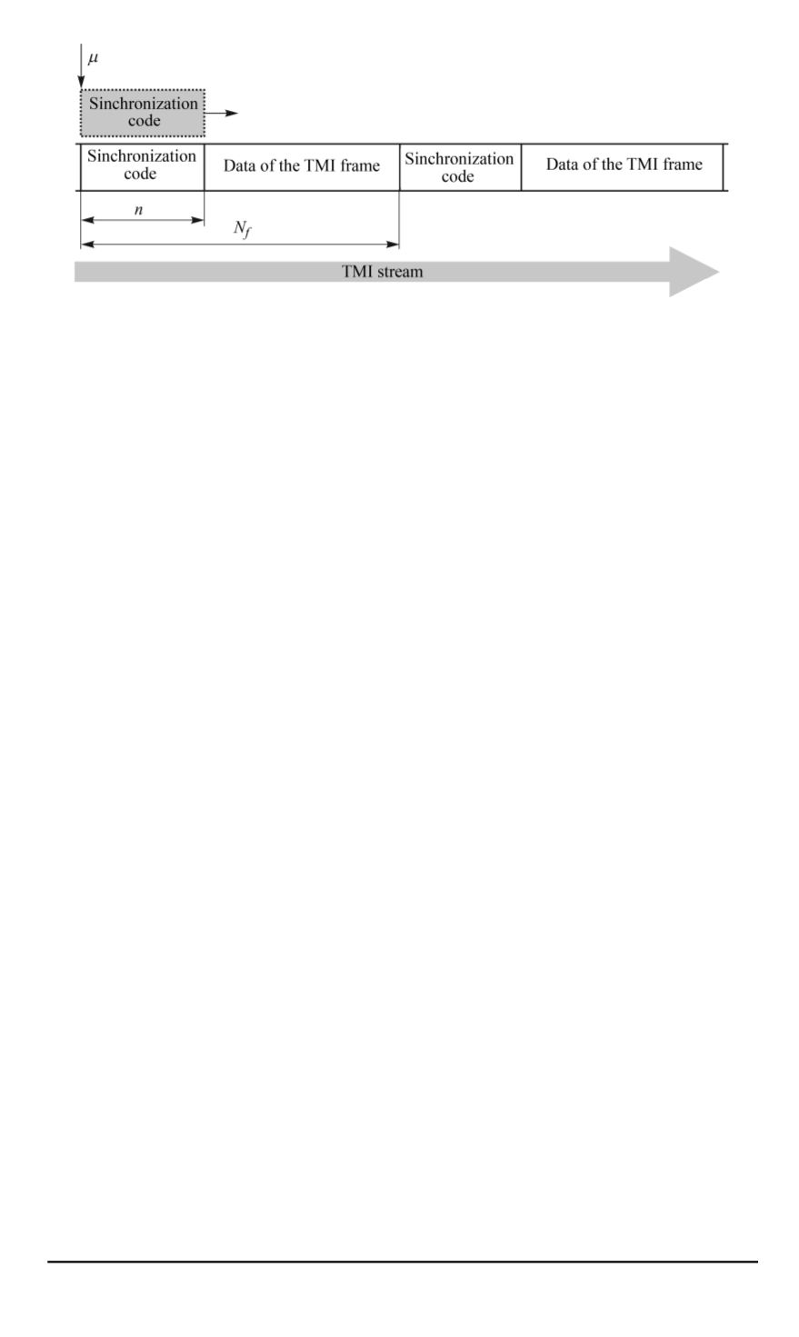

Fig. 1. The structure of the synchronized TMI frame
presents the results of the research into the frame synchronization recovery
system in the TMI stream of IRIG-106 standard filled with information
from sensors. Parameters of the synchronization system are chosen based
on experimental data and they are compared with the theoretically obtained
values.
In all operational modes the synchronization code detection is typically
performed using a correlation process in which an input message is
being continuously compared with the synchronization code known by
the correlation algorithm. With a relatively high correlation between the
synchronization code and the messages symbols, the code is considered to
be detected.
The task of the synchronization code detection is to determine the
location of the synchronization code in each TMI frame (Fig. 1) in the
received bitstream:
μ
s,l
= argmax
μ
l
∈
[(
l
−
1)
N
f
+1;
lN
f
]
L
(
μ
)
,
(1)
where
μ
is the location of the detected synchronization code in the bitstream
d
=
{
d
1
, d
2
, d
3
, . . .
}
;
S
=
{
s
1
, s
2
, . . . , s
n
}
— is
n
-bit synchronization code
being used;
l
— is a serial number of the detected frame in the stream
d
;
N
f
— is the TMI frame length;
L
(
μ
)
— is a correlation process described
in [5–7], which is defined by the formula
L
(
μ
) =
n
X
k
=1
s
k
d
k
+
μ
.
(2)
The correlation coefficient in each state of the synchronizer is continu-
ously compared with a predetermined threshold
ε
for each state. While
this value does not exceed the threshold value, the synchronizer remains
in its current state, but when the threshold is exceeded, the synchronizer
proceeds to the previous one.
118 ISSN 0236-3933. HERALD of the BMSTU. Series Instrument Engineering. 2015. No. 2


