


 3 / 9
3 / 9

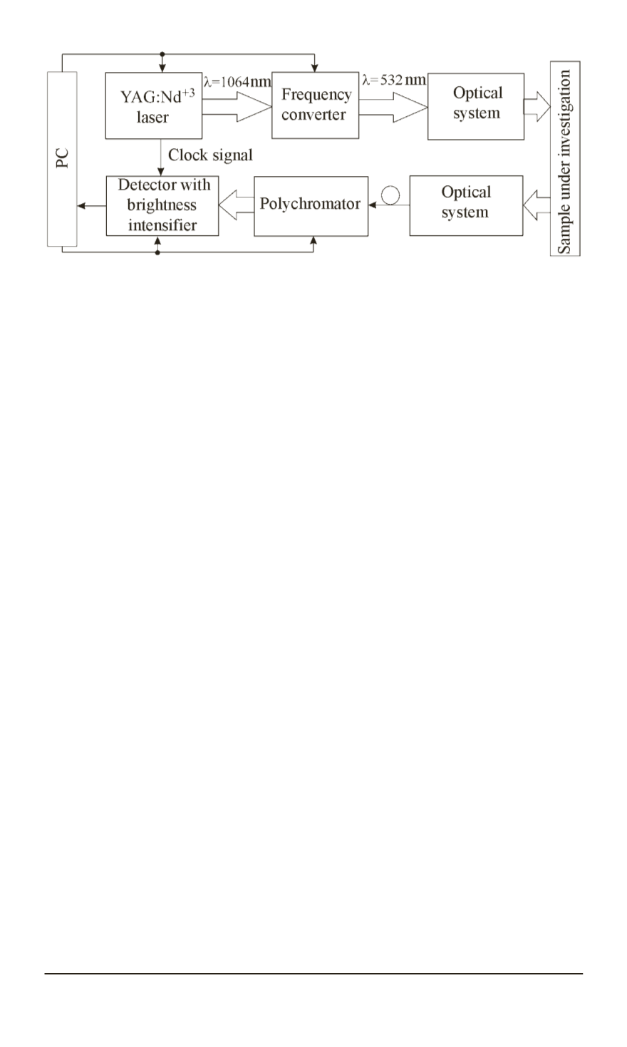
Fig. 1. Block diagram of the laboratory setup
The second harmonic of YAG:Nd laser is used as the source of
excitation of fluorescence radiation. Registration subsystem of the fluores-
cence radiation is designed on the basis of both the polychromator and
highly sensitive matrix detector with amplified brightness.
Plants’ fluorescence spectra were measured on the setup in the range of
595. . .800 nm. Both the fluorescence spectrum and reflected laser radiation
intensity were registered simultaneously at the wavelength of 532 nm.
The main parameters of the laboratory setup and the laser source are
shown below.
The main parameters of the laboratory facility
The spectrum registration range, nm . . . . . . . . . . . . . . . . . . 595–800
The diameter of the receiver lens, mm . . . . . . . . . . . . . . . . 15
The distance to the plant, m . . . . . . . . . . . . . . . . . . . . . . . . .
∼
1
The main parameters of the laser
The energy of the laser pulse, mJ . . . . . . . . . . . . . . . . . . . . . . . . . . . . . . 2.1
Pulse duration, ns . . . . . . . . . . . . . . . . . . . . . . . . . . . . . . . . . . . . . . . . . . . .
<
7
Wavelength, nm . . . . . . . . . . . . . . . . . . . . . . . . . . . . . . . . . . . . . . . . . . . . . . 532
Pulse rate, Hz . . . . . . . . . . . . . . . . . . . . . . . . . . . . . . . . . . . . . . . . . . . . . . . . up to 500
Mode composition . . . . . . . . . . . . . . . . . . . . . . . . . . . . . . . . . . . . . . . . . . . . ТЕМ00
Beam divergence, mrad . . . . . . . . . . . . . . . . . . . . . . . . . . . . . . . . . . . . . . .
<
3
Beam diameter, mm . . . . . . . . . . . . . . . . . . . . . . . . . . . . . . . . . . . . . . . . . . 0.8
Stability of the pulse energy, RMS, . . . . . . . . . . . . . . . . . . . . . . . . . . . .
<
1
Cooling . . . . . . . . . . . . . . . . . . . . . . . . . . . . . . . . . . . . . . . . . . . . . . . . . . . . . . Air
Dimensions, mm:
transmitter unit . . . . . . . . . . . . . . . . . . . . . . . . . . . . . . . . . . . . . . . . . . .
164
×
274
×
93
power supply unit . . . . . . . . . . . . . . . . . . . . . . . . . . . . . . . . . . . . . . . .
340
×
365
×
290
Power consumption, W . . . . . . . . . . . . . . . . . . . . . . . . . . . . . . . . . . . . . . .
<
300
Experimental study of fluorescence spectra included a polychromator
wavelength calibration as a preliminary step using standard methods and
ISSN 0236-3933. HERALD of the BMSTU. Series “Instrument Engineering”. 2015. No. 2 73