optic gyros, such as the GG1308 of Honeywell company and the
μFORS
of LITEF company. The required performance of the MOG to be developed
is shown in Table 1
Тable 1
Characteristics of the MOG to be developed
Range of measurement
500 deg/s
Resolution
0.1–1 deg/h
Bias stability
1–10 deg/h
Scale factor errors
100–500 ppm
Bandwidth
200 Hz
For investigating the proposed re-entrant interferometer MOG, a fiber
anlogue experimental setup was developed at Tsinghua University, in which
the elements of conventional IFOG are used, such as the high quality
superluminescent diode (SLD), the multi-functional IO phase modulator
chip (MIOC), and the all digital closed loop electronics (ADCL).
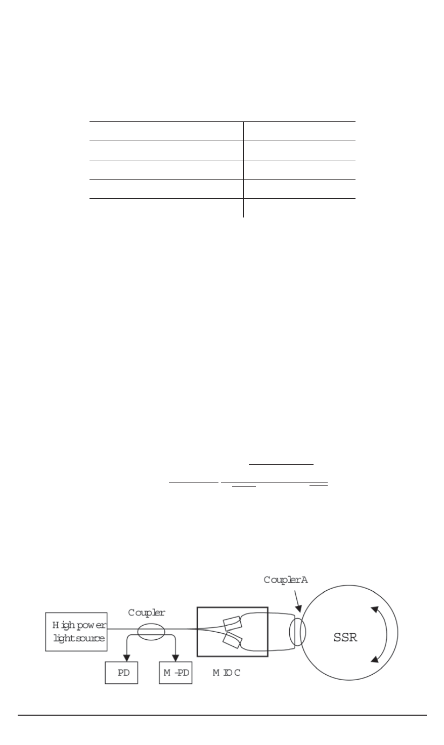
Proposed interferometer system configuration.
The setup of the
proposed MOG system and the main elements are shown in Fig. 1 and
Table 2, respectively. In the system configuration, an input / output coupler
A is designed for transmitting the bi-directional light beams into the Sagnac
sensing ring (SSR) and then back to the MIOC.
In case of open loop operation, the optical intensity detected by the
photodiode (PD) is the sum of the optical responses of light beams with
different number of round-trips. The resolution of the MOG system can be
determined as
ΔΩ
min
=
λc
2
πMLD
4
hν
·
T
(
φ
s
)
√
η
D
t
i
·
S
(
φ
s
)
√
P
in
,
where
M
is the number of round-trips circulated;
λ, c
are the wavelength
and the light speed, respectively;
L, D
are the length and the diameter of
SSR, respectively;
h
is Plank’s constant;
ν
is the light angular frequency;
Fig. 1. The system configuration of re-entrant interferometer optic gyro
110 ISSN 0236-3933. Вестник МГТУ им. Н.Э. Баумана. Сер. “Приборостроение”. 2005. № 4


